CAMSHAFTS
The Basics
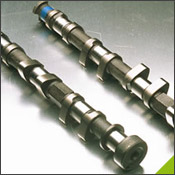
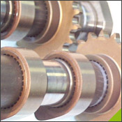
The key parts of any camshaft are the lobes. As the camshaft spins, the lobes open and close the intake and exhaust valves in time with the motion of the piston. It turns out that there is a direct relationship between the shape of the cam lobes and the way the engine performs in different speed ranges.
To understand why this is the case, imagine that we are running an engine extremely slowly -- at just 10 or 20 revolutions per minute (RPM) -- so that it takes the piston a couple of seconds to complete a cycle. It would be impossible to actually run a normal engine this slowly, but let's imagine that we could. At this slow speed, we would want cam lobes shaped so that:
- Just as the piston starts moving downward in the intake stroke (called top dead center, or TDC), the intake valve would open. The intake valve would close right as the piston bottoms out.
- The exhaust valve would open right as the piston bottoms out (called bottom dead center, or BDC) at the end of the combustion stroke, and would close as the piston completes the exhaust stroke.
This setup would work really well for the engine as long as it ran at this very slow speed.
When you increase the RPM, however, this configuration for the camshaft does not work well. If the engine is running at 4,000 RPM, the valves are opening and closing 2,000 times every minute, or 33 times every second. At these speeds, the piston is moving very quickly, so the air/fuel mixture rushing into the cylinder is moving very quickly as well.
 When the intake valve opens and the piston starts its intake stroke, the air/fuel mixture in the intake runner starts to accelerate into the cylinder. By the time the piston reaches the bottom of its intake stroke, the air/fuel is moving at a pretty high speed. If we were to slam the intake valve shut, all of that air/fuel would come to a stop and not enter the cylinder. By leaving the intake valve open a little longer, the momentum of the fast-moving air/fuel continues to force air/fuel into the cylinder as the piston starts its compression stroke. So the faster the engine goes, the faster the air/fuel moves, and the longer we want the intake valve to stay open. We also want the valve to open wider at higher speeds -- this parameter, called valve lift, is governed by the cam lobe profile. When the intake valve opens and the piston starts its intake stroke, the air/fuel mixture in the intake runner starts to accelerate into the cylinder. By the time the piston reaches the bottom of its intake stroke, the air/fuel is moving at a pretty high speed. If we were to slam the intake valve shut, all of that air/fuel would come to a stop and not enter the cylinder. By leaving the intake valve open a little longer, the momentum of the fast-moving air/fuel continues to force air/fuel into the cylinder as the piston starts its compression stroke. So the faster the engine goes, the faster the air/fuel moves, and the longer we want the intake valve to stay open. We also want the valve to open wider at higher speeds -- this parameter, called valve lift, is governed by the cam lobe profile.
Any given camshaft will be perfect only at one engine speed. At every other engine speed, the engine won't perform to its full potential. A fixed camshaft is, therefore, always a compromise. This is why carmakers have developed schemes to vary the cam profile as the engine speed changes.
There are several different arrangements of camshafts on engines. We'll talk about some of the most common ones. You've probably heard the terminology:
- Single overhead cam (SOHC)
- Double overhead cam (DOHC)
- Pushrod
Single Overhead Cams
This arrangement denotes an engine with one cam per head. So if it is an inline 4-cylinder or inline 6-cylinder engine, it will have one cam; if it is a V-6 or V-8, it will have two cams (one for each head).
The cam actuates rocker arms that press down on the valves, opening them. Springs return the valves to their closed position. These springs have to be very strong because at high engine speeds, the valves are pushed down very quickly, and it is the springs that keep the valves in contact with the rocker arms. If the springs were not strong enough, the valves might come away from the rocker arms and snap back. This is an undesirable situation that would result in extra wear on the cams and rocker arms.
On single and double overhead cam engines, the cams are driven by the crankshaft, via either a belt or chain called the timing belt or timing chain. These belts and chains need to be replaced or adjusted at regular intervals. If a timing belt breaks, the cam will stop spinning and the piston could hit the open valves.
Double Overhead Cam
A double overhead cam engine has two cams per head. So inline engines have two cams, and V engines have four. Usually, double overhead cams are used on engines with four or more valves per cylinder -- a single camshaft simply cannot fit enough cam lobes to actuate all of those valves.
The main reason to use double overhead cams is to allow for more intake and exhaust valves. More valves means that intake and exhaust gases can flow more freely because there are more openings for them to flow through. This increases the power of the engine.
Pushrod Engines
Like SOHC and DOHC engines, the valves in a pushrod engine are located in the head, above the cylinder. The key difference is that the camshaft on a pushrod engine is inside the engine block, rather than in the head.
The cam actuates long rods that go up through the block and into the head to move the rockers. These long rods add mass to the system, which increases the load on the valve springs. This can limit the speed of pushrod engines; the overhead camshaft, which eliminates the pushrod from the system, is one of the engine technologies that made higher engine speeds possible.
The camshaft in a pushrod engine is often driven by gears or a short chain. Gear-drives are generally less prone to breakage than belt drives, which are often found in overhead cam engines.
Variable Valve Timing
There are a couple of novel ways by which carmakers vary the valve timing. One system used on some Honda engines is called VTEC.
VTEC (Variable Valve Timing and Lift Electronic Control) is an electronic and mechanical system in some Honda engines that allows the engine to have multiple camshafts. VTEC engines have an extra intake cam with its own rocker, which follows this cam. The profile on this cam keeps the intake valve open longer than the other cam profile. At low engine speeds, this rocker is not connected to any valves. At high engine speeds, a piston locks the extra rocker to the two rockers that control the two intake valves.
Some cars use a device that can advance the valve timing. This does not keep the valves open longer; instead, it opens them later and closes them later. This is done by rotating the camshaft ahead a few degrees. If the intake valves normally open at 10 degrees before top dead center (TDC) and close at 190 degrees after TDC, the total duration is 200 degrees. The opening and closing times can be shifted using a mechanism that rotates the cam ahead a little as it spins. So the valve might open at 10 degrees after TDC and close at 210 degrees after TDC. Closing the valve 20 degrees later is good, but it would be better to be able to increase the duration that the intake valve is open.
Ferrari has a really neat way of doing this. The camshafts on some Ferrari engines are cut with a three-dimensional profile that varies along the length of the cam lobe. At one end of the cam lobe is the least aggressive cam profile, and at the other end is the most aggressive. The shape of the cam smoothly blends these two profiles together. A mechanism can slide the whole camshaft laterally so that the valve engages different parts of the cam. The shaft still spins just like a regular camshaft -- but by gradually sliding the camshaft laterally as the engine speed and load increase, the valve timing can be optimized.
Several engine manufacturers are experimenting with systems that would allow infinite variability in valve timing. For example, imagine that each valve had a solenoid on it that could open and close the valve using computer control rather than relying on a camshaft. With this type of system, you would get maximum engine performance at every RPM. Something to look forward to in the future...
|
